
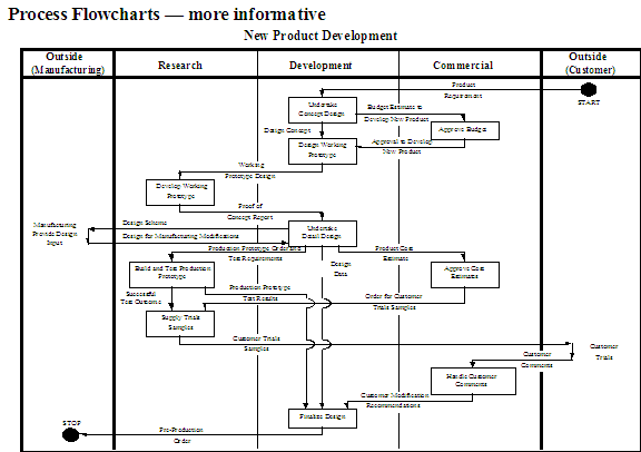
BPI Technique - Process Mapping - PMa
Description
- The depiction of processes in pictorial diagrams.
- Activities and their relationship and sequence
- The relationship of activities and functions
- Steps that compose activities
- What purpose each step provides
- The relationship and sequence of the steps e.g. inputs/outputs, etc.
When to Use
- Process mapping can be used at all three of the major tiers of process modeling: business-model processes, high-level process models and “desk-top procedures” level. It can be used for both "As-Is” Process Assessment and "To-Be" Process Model deliverables.
Approach
Process-modeling documentation is dependent on the purpose of the model and the subsequent tool that is chosen to document the processes. As defined below, there are many choices depending on needs. These range from simple models for presentation and communication purposes to complex models for developing applications in the future. When developing the activities in the process models, use tools directly related to process development. When the processes have been sufficiently developed, transfer them to the process models described here.
These models are based on levels of detail. Block diagrams are often used at the first “high level” or process level. The second level of decomposition is the “activity” level, which is represented by process flowcharts, and, finally, the third level is the “step” level represented by the activity models. Only areas that will yield benefits if analyzed and designed should be decomposed into the more detailed levels.
- Identify the process to be mapped
- Create a process diagram for the selected processes
- Use block diagrams to identify the major activities within the process
- Identify and map the activities for the selected activities
- Create process flowcharts connecting activities in sequence by functional area.
- Identify functions related to process.
- Identify the start and stop points of process.
- Utilize activities developed in the block diagrams.
- Further define activities.
- Map activities to functions.
- Determine and match inputs and outputs with adjacent blocks.
- Identify the sequence of activities (activities may be concurrent or sequential).
- Describe the relationship of activities along connection lines.
- Create activity models
- Identify core activity data
- Collect data on each activity, and describe activity in detail.
- Select activities to decompose.
- Only decompose those areas where problems have been identified or may be identified through the decomposition.
- Include as criteria for selection: effectiveness, efficiency and opportunity
- Classify activity steps and create symbols for each category.
- Operation: changes state of product toward final form or to meet internal requirements.
- Store: removes item from process for later retrieval (add qualifier if permanently stored versus temporarily stored versus destroyed or discarded).
- Decision: presents separate options.
- Move/transport: any move other than hand-to-hand transfer between operations. May be items, data or information moved to or from position/unit.
- Inspection/test: internal inspection (on-line review of own work), external inspection (independent test of others’ work)
- Delay: in process waiting time (queue, awaiting instructions, process related) Connector: provides mechanism to document linkages between process flow symbols on the process diagram, which may be separated and difficult to connect without making the diagram cluttered.
- Create columns or rows.
- Outside: documents, materials or information entering or leaving the function or unit in which the activity occurs
- Functions e.g. functional area, departments, job titles etc. (work moving from one function to another should be recorded under the new function column/row)
- Other areas involved in the activity (an activity may involved more than one unit)
- Note that downward or side-flow movement along columns or rows represents time continuation and sequential steps.
- Place steps within their categories in the columns/rows.
- Identify flow with solid lines drawn between activities with arrows pointing to the next step symbol.
- Identify value-added operations (shade objects).
- Add text to describe step, time taken, etc.
- Verify data, information and flows
Guidelines
Tactics/Helpful Hints
- Ensure that process decomposition only go as deep as is needed to identify problems or describe solutions that you are trying to fix.
- Be aware that each activity or step should only decompose into a maximum of 1-5 other steps. This ensures that the level of detail is consistent across process flow levels.
- Know that consistency is the key to a clear, organized chart.
- Understand that common pitfalls to process mapping are incomplete process diagrams and premature problem-solving.
Examples


No comments :
Post a Comment